NEMA Wiring Schematic Manual for Electrical Experts
Nearly seventy percent of electrical malfunctions across facilities stem from inadequate wiring practices. Such data underlines the necessity of adhering to established guidelines, spotlighting NEMA wiring diagrams’ significance for electrical specialists. Via these drawings, wiring setups that meet both performance efficiency and highest security criteria are delineated.
The purpose of this manual is to equip electrical practitioners with profound understanding into NEMA standards. Stressing the importance of proper electrical setups is crucial. By learning these guidelines, practitioners can drastically minimize the risk of hazards and confirm they meet safety measures backed by Installation Parts Supply. Knowledge in l 14 30 plug is essential whether creating novel setups or repairing existing ones, as it improves the capability to deliver secure and dependable electrical answers.
Main Points
- NEMA wiring diagrams are essential for guaranteeing electrical safety and compliance.
- Proper wiring practices can minimize electrical issues substantially.
- Grasping NEMA criteria boosts the performance of electrical arrangements.
- Installation Parts Supply encourages adherence to safety protocols in electrical work.
- NEMA schematics support a broad spectrum of uses across various industries.
Grasping NEMA Criteria and Their Significance
NEMA standards are crucial in the electrical domain, directing security and operation meticulously. Crafted by the National Electrical Manufacturers Association, they define pivotal benchmarks for creating, testing, and marking electrical equipment. It ensures uniformity and trustworthiness across all electrical installations, which is priceless.
Identify the NEMA Norms?
NEMA designations vary from classes 1 to 13. Every level delineates the parameters suitable for electrical appliances to operate effectively. For example, NEMA 1 provides fundamental indoor safeguarding but is missing dust shielding. Conversely, NEMA 4 ensures equipment is watertight, a necessity for surviving considerable water immersion. Grasping these categories is essential in selecting suitable appliances.
How NEMA Standards Are Important for Electrical Safety
The impact of NEMA norms in guaranteeing electrical safety is substantial. They play a significant part in minimizing electric shock, apparatus malfunctions, and burn risks. Proper adherence to NEMA standards empowers equipment to perform safely under certain ambient conditions. For outdoor deployment, NEMA 3 classifications offer protection against the weather, shielding the apparatus from harsh conditions like rain and snow. In zones prone to explosions, classifications such as NEMA 7, 8, and 9 are critical for upholding security.
Applications of NEMA Norms in Wiring Drawings
The implementation of NEMA standards in wiring drawings is crucial for safe, optimal electrical installations. These schematics make use of uniform symbols and formats originating from NEMA classifications, simplifying the understanding of intricate electrical configurations. This standardizing is beneficial. It fosters transparency, consistency, and reduces errors, thereby enhancing electrical protection across residential and commercial environments.
NEMA Wiring Schematic Essentials
NEMA wiring schematics are essential for electrical experts, rendering intricate connections clear. They describe the junctions and components in different setups. By understanding the components, kinds, and symbols of NEMA diagrams, electricians can improve their performance in setups and upkeep.
Components of NEMA Wiring Drawings
NEMA schematics comprise essential components for particular electrical installations. You’ll discover wiring terminals, interfaces, and other hardware for reliable connections. Every piece guarantees energy is spread effectively, in accordance with safety guidelines.
Categories of NEMA Wiring Drawings
NEMA employs different schematics, like connection schematics and circuit layouts. Such diagrams detail device associations, while layouts display power flow. Selecting the appropriate diagram helps with troubleshooting and deployment.
Typical Notations Used in NEMA Wiring Schematics
Notations in wiring diagrams are crucial for unambiguous conveyance. They depict switches, networks, and connectors. Understanding these notations aids groups comprehend drawings correctly. This ensures installations comply with NEMA norms.
NEMA Wiring Diagram Features
For electrical experts, comprehending the key elements of accurate electrical wiring diagrams is crucial. These diagrams provide both clarity and thoroughness, synchronizing installations with NEMA norms. They demand precise annotation and sizing to curtail setup mistakes. Such practices promote a safer and more efficient operational setting.
Key Attributes of Accurate Electrical Wiring Schematics
Correct electrical wiring drawings are essential in electrical projects. They embody important features such as:
- Lucidity: Diagrams are required to be simple, lowering the risk of misinterpretation.
- Completeness: They need to contain all key elements, connections, and electrical standards.
- Adherence to Standards: Complying with NEMA criteria is mandatory for securing safety and operation.
- Thorough Annotation: Unambiguous markings on each component are fundamental for grasping and error prevention.
- Correct Scaling: The scales should replicate the actual setup to represent the system correctly.
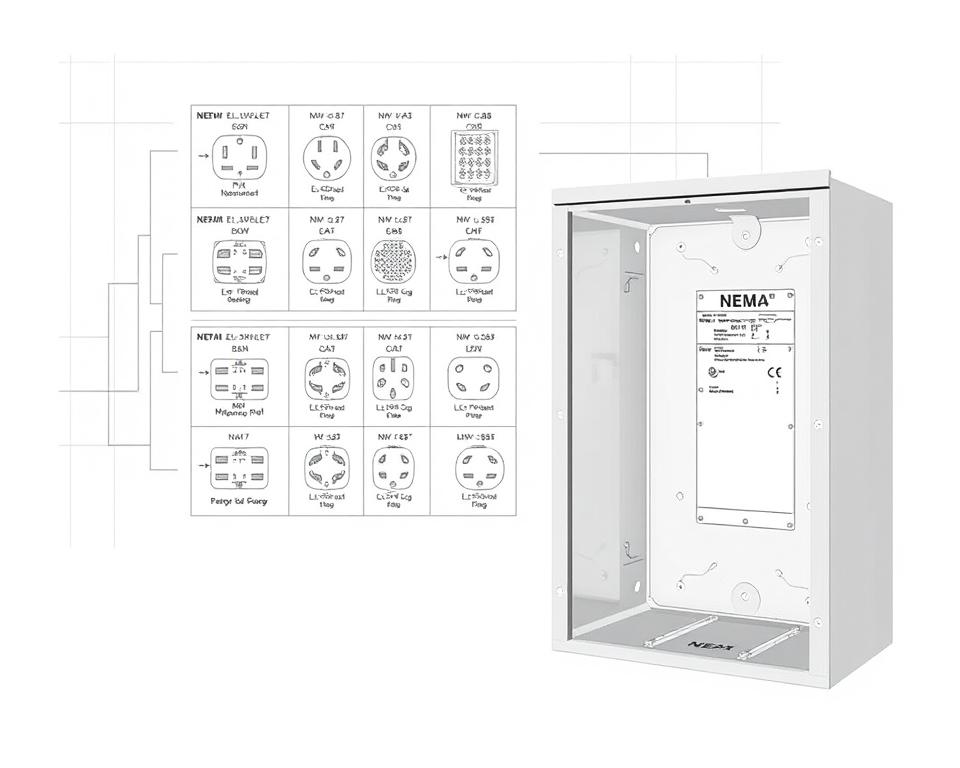
Grasping NEMA Coupler Layout
Grasping NEMA connector configuration is vital for making proper connections in electrical setups. Understanding of distinct pin setups ensures safety and device operation. There are a range of NEMA interfaces, designed for specific voltages and currents, encompassing:
| Connector Model | Amperage Rating | Voltage Rating |
|---|---|---|
| L5-15 | 15A | 125V |
| L5-20 | 20A | 125V |
| L14-20 | 20A | 125/250V |
| L1430C | 30A | 125/250V |
| L620C | 20A | 250V |
| L1430C | 30A | 125/250V |
| L630R | 30A | 250V |
Understanding NEMA connector configurations is vital for secure connections, improving performance. It’s imperative to pair connectors with appliances correctly using locking or flat blade styles, to dodge safety risks.
NEMA Device Wiring
NEMA device wiring encompasses various arrangements for safe electrical device connections. These guidelines ensure that appliances operate in unison securely, reducing risk. Understanding the different NEMA devices and their wiring is vital for technicians.
Various Categories of NEMA Appliances
NEMA categorizes units by type based on voltage levels and flow needs. Primary configurations are:
- 2-Pole 2-Wire
- 2-Pole, 3-Wire with Grounding
- 3-Pole, 3-Wire
- 3-Pole, 4-Wire with Grounding
- 4-Pole, 4-Wire
- 4-Pole 5-Wire Grounding
These setups find use in residences and factories, supporting 125V, 208V, and 480V.
NEMA Outlet Wiring Explained
NEMA plug wiring varies to accommodate multiple electrical demands, with rotary-lock types delivering secure connections in vibrating settings. Such as, the L5-15 plug is rated for 15 amperes, frequently used in business sites, whereas the L14-20 is intended for 20 amperes at 125/250 voltage.
The NEMA naming scheme helps in selecting the appropriate plugs, spotlighting characteristics like polarity and grounding. Such accuracy ensures that equipment function safely.
NEMA Receptacle Wiring Instructions
Correct wiring of NEMA receptacles aligns with electrical codes and safety guidelines. For instance, L530R receptacles are rated for 30 A at 125 volts, with L630R options for 250 voltage. Proper grounding is crucial to avoid electrical mishaps.
Selecting certified NEMA plugs and receptacles secures secure, regulation-compliant configurations. It’s critical to check formal guidelines when installing.
NEMA Motor Wiring and Implementations
NEMA motor wiring is crucial in electrical systems, particularly for manufacturing use. Grasping how NEMA motor configuration works guarantees that machines are set up for best performance. These motors, like single-phase and tri-phase types, require accurate wiring to work safely and optimally.
Overview of NEMA Motor Wiring
Understanding NEMA motor wiring necessitates familiarity of junctions and arrangements. The majority of three-phase motors offer dual-voltage, meaning they can run on both low (208-230V) and high voltage levels (460V). High voltage wiring allows motors to draw less current than at low voltage. High voltage perks comprise smaller wires for the supply, a significant benefit for motors exceeding 10 HP.
While both NEMA and IEC devices are employed in the market, NEMA models are typically bigger and more costly than IEC ones for below 100 HP applications. NEMA trips span size 00 to 9, fit for various functions. A common characteristic in NEMA controllers is a Fault Class of 20, designed to trip when a motor’s current surpasses 6-fold the Full Load Amperage (FLA) in 10 secs.
Selecting the Correct NEMA Motor Configuration
Opting for the appropriate NEMA motor configuration affects overall efficiency and security. A typical three-wire control circuit utilizes three wires for a start/stop pushbutton interface, enabling direct motor control. Frequent three-phase configurations comprise the 12 Lead Dual Voltage and 6 Lead, supporting Wye and Delta connections.
IEC motor starters commonly feature phase failure detection, increasing safety. They also include configurable Trip Ratings for tailored protection in low voltage operations. Additionally, many units have thermal protection, essential for Single Phase and Dual Voltage systems.
| Setup Type | Power Type | Amperage | Common Application |
|---|---|---|---|
| 12 Lead Dual Voltage | Dual Voltage (208-230V / 460V) | Varies by motor size | Applications with Wye Start and Delta Run |
| 6 Lead | Single or Dual Voltage | Up to 32 amps | Both Wye and Delta arrangements |
| Single Phase | One Voltage | Varies (1-5 amps adjustment) | Dual Speed and Dual Winding setups |
| Delta Connection | High Voltage | Variable | Various applications including Current Transformers |
Wrapping It Up
Grasping NEMA wiring schematics and norms is vital for electrical specialists aiming to enhance their skills and adhere to electrical safety standards. These principles not only ensure secure and effective electrical setups but also avoid hazards linked to incorrect wiring. As discussed, complying with NEMA norms results in the enhanced capability of diverse NEMA units and configurations.
For electricians, the availability of superior supplies can profoundly influence the outcome of their projects. Installation Parts Supply offers a extensive range of wiring products in accordance with NEMA criteria. This empowers specialists to access essential elements for fulfilling these significant standards. Premium materials and profound knowledge of NEMA wiring schematics substantially improve installation security and effectiveness.
Throughout electrical installations, always prioritize safety and precision as a priority. Becoming well-versed in NEMA criteria provides the knowledge necessary for applying best practices correctly. This guarantees that each electrical connection established conforms to superior standards.
Common Questions
Identify NEMA wiring schematics?
NEMA wiring diagrams display the setups and connections of NEMA-standard electrical appliances. They comply with safety and operational norms established by the National Electrical Manufacturers Association.
Why are NEMA standards important for electrical protection?
NEMA criteria are essential to establishing safety and performance benchmarks for electrical devices. These guidelines enable electrical specialists lower electric shock, operational errors, and fire risk.
What components are vital in a NEMA wiring drawing?
Key elements in a NEMA wiring drawing comprise circuit configurations and connection schematics. These diagrams also feature comprehensive labels and show the electrical system’s diverse parts precisely for setups.
What types of NEMA wiring drawings are available?
Various NEMA wiring drawings cater to various needs, including power distribution circuits and interconnection diagrams for components. Each layout plays a unique role in electrical setups.
What are common symbols employed in NEMA wiring diagrams?
Typical symbols in these drawings depict controls, fuses, receptacles, and other elements. Employing these symbols encourages clear communication and correct understanding of wiring schematics.
Identify the key characteristics of accurate electrical wiring schematics?
Precision in electrical wiring diagrams is characterized by their lucidity, completeness, and detailed annotation. They should conform to NEMA standards to avoid mistakes in setup.
What is a NEMA connector configuration?
A NEMA connector configuration depicts electrical linkages at a connector, indicating particular pin assignments. This ensures secure and effective connections in electrical systems.
Identify the different kinds of NEMA appliances?
NEMA devices include various electrical outlets and connectors, like connectors and receptacles. They are designed for various amperage and power criteria to meet particular usage needs.
How is NEMA plug wiring arranged?
NEMA plug wiring hinges on defined current and voltage levels needs, complying with safety standards and regulatory standards for diverse electrical applications.
What guidelines are there for NEMA receptacle wiring?
Recommendations for wiring NEMA sockets emphasize following electrical regulations, guaranteeing correct charge alignment, and choosing appropriate gauge sizes. This sustains both protection and operation in electrical installations.
Describe how to wire a NEMA motor properly?
To set up a NEMA motor, one must grasp its specific single-phase or tri-phase configuration. Choosing the appropriate wiring approach is essential, plus maintaining electrical protection for optimized motor efficiency.
What should I consider when choosing a NEMA motor setup?
Choosing a NEMA motor arrangement demands an analysis of the project’s energy requirements and performance traits. It’s also essential to verify alignment with current equipment for guaranteed efficiency and protection.